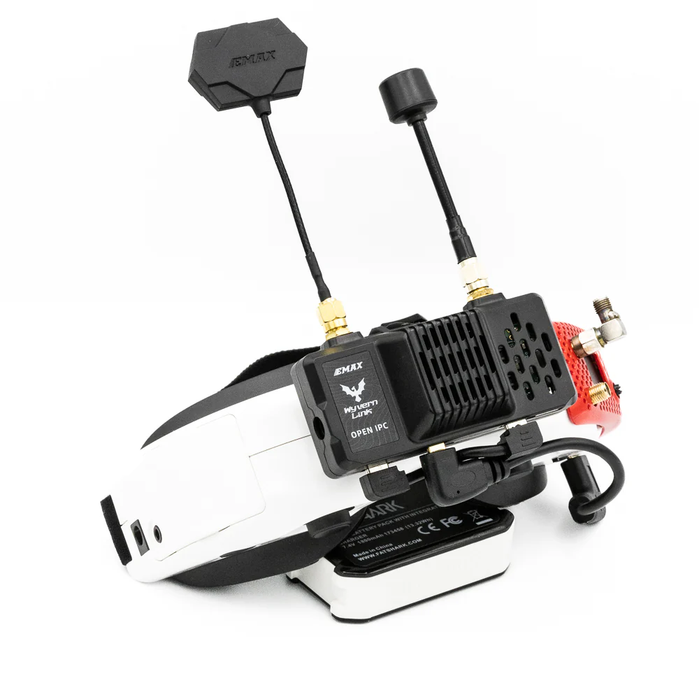
Emax Wyvern Link VRX
Specifications
| SOC board | Radxa ZERO 3W with 32GB of eMMC |
|---|---|
| WiFi chip | RTL8812AF1 (5MHz, 10MHz, 20MHz, 40Mhz) |
| Bracket hole spacing | 21mm*21mm (Fatshark, Skyzone standard) |
| Size | 88mm(width), 55.5mm(height), 40.5mm(depth) |
| Weight | 101.2g (complete kit) / 87.7g (with antenna) / 71.6g (without antenna) |
| Antennas | SMA connector (kit: LHCP Omni + Patch) |
| Factory Firmware | SBC v1.9.6 (v1.9.9?) |
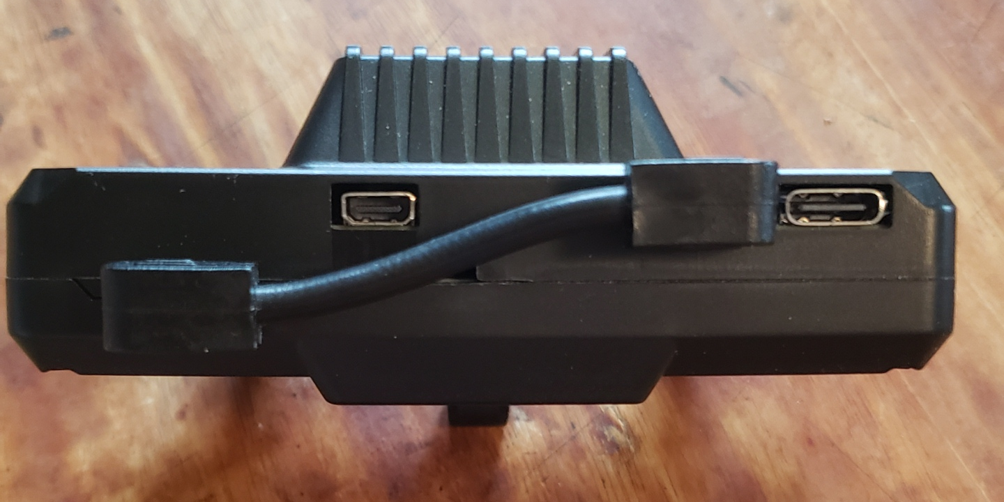
| Included cables | short USB, split-Y power cable, micro-HDMI to mini HDMI |
Boards
RADXA ZERO 3W
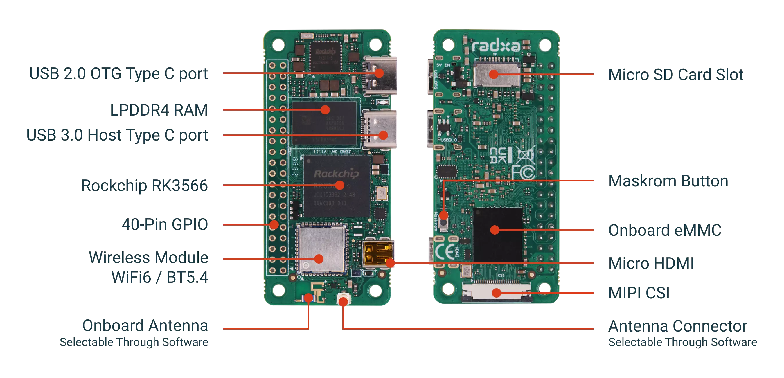
eMMC is Samsung KLMBG2JETD-B041 32GB
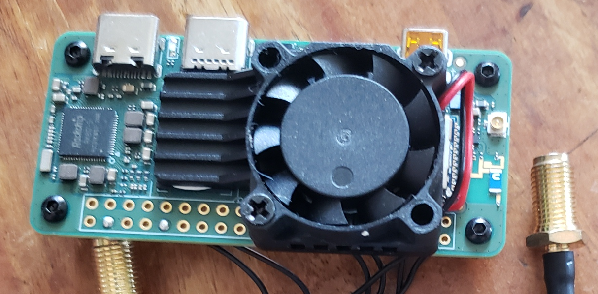
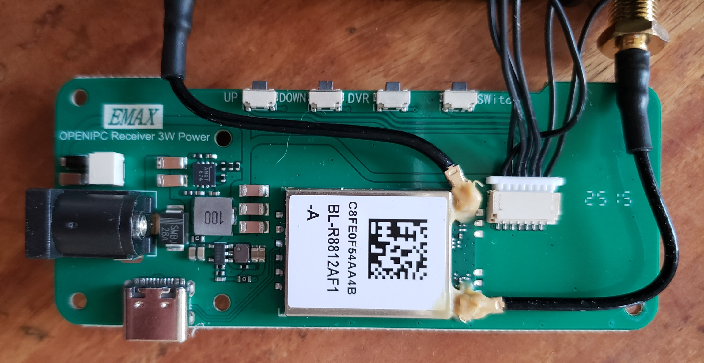
Emax custom power, wifi and buttons board
Basic setup
What you need
-
Goggles or portable monitor with HDMI input.
-
2S-6S battery with barrel jack or USB powerbank
Hardware Setup
-
Connect supplied USB cable between internal boards
-
Connect the antennas to VRX
-
Mount bracket onto goggles if Fatshark or Skyzone. If other googles or portable monitor, 3D print custom bracket or use velcro or double-sided tape.
-
Connect HDMI cable between VRX and goggles or monitor. VRX Radxa uses micro-HDMI.
-
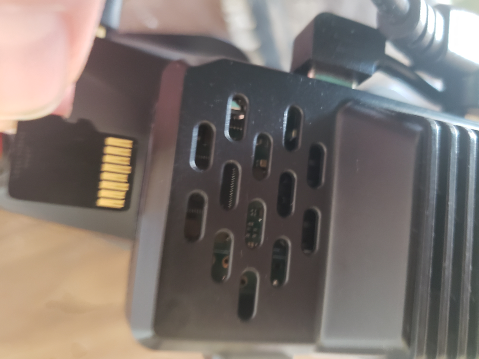
(optional) Insert a formatted micro SD card into the VRX. The slot doesn’t autocorrect so insert with the connectors facing up when the fan faces up.
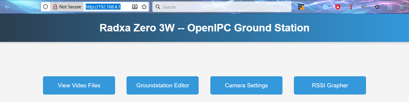
Default firmware interface
The default firmware on the internal eMMC is SBC v1.9.9 and has a simple menu and button system.
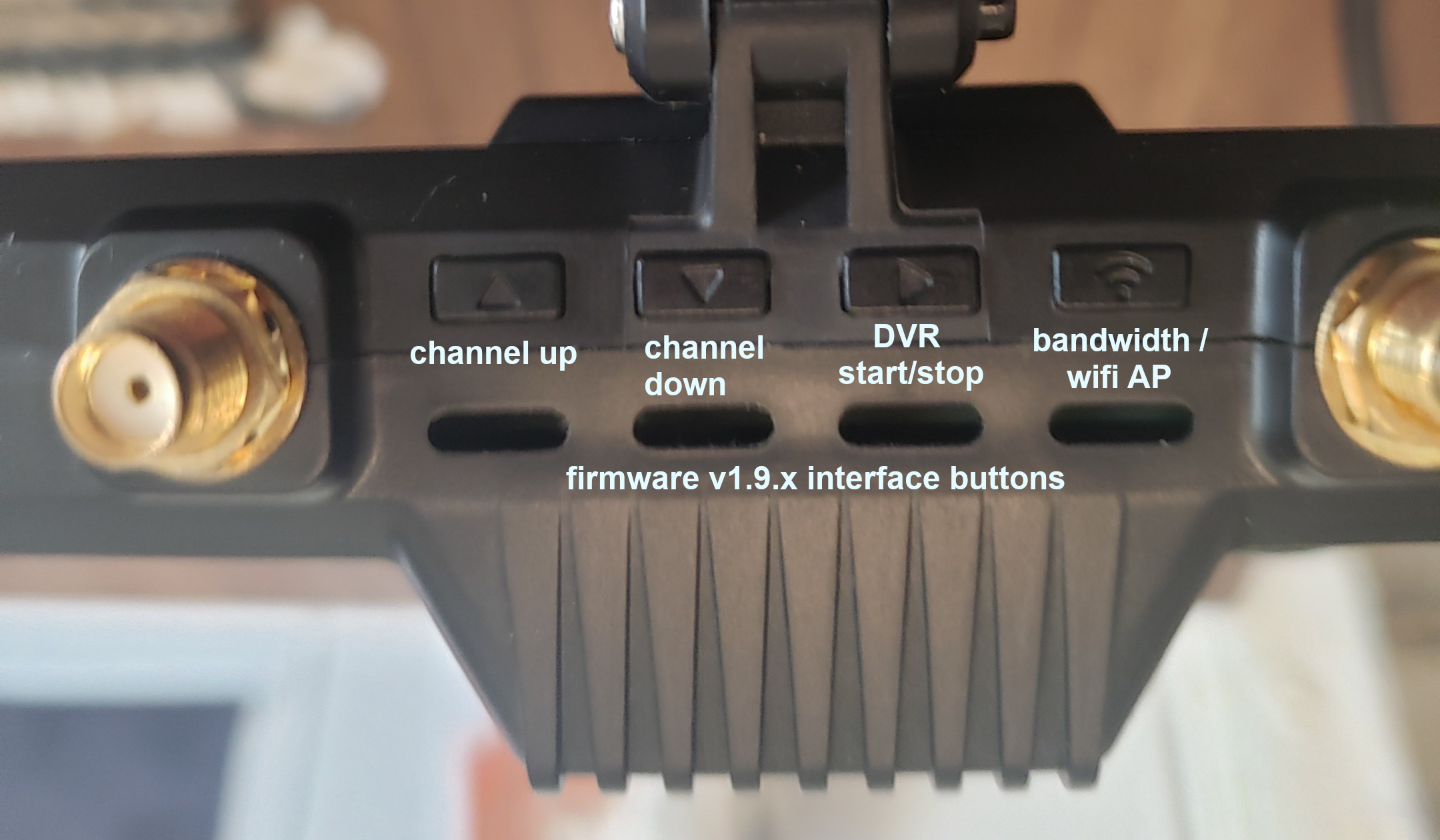
- Up and down buttons change the wifi channel
- side arrow starts/stops DVR recording
- The right most “wifi” button has two functions
- short press changes the bandwidth
- long press activates the wifi access-point (AP). VRX will appear on your local wifi network as SSID: RadxaGroundstation password: radaxaopenipc
Groundstation WebUI can be accessed at http://192.168.4.1/
How to get or change gs.key with v1.9.9 firmware
- Insert an empty, formatted micro SD into the VRX.
- When you first power up your VRX, the device will create a ‘user’ file and a ‘gs.key’ file.
- Mount SDcard on PC and either replace the gs.key file to match your VTXs or use this gs.key on all your VTXs.
- Reinsert the SDcard into the VRX and on next boot it will replace the internal gs.key with the one on the SDcard.
Basic setup summary
The VRX is configured with the default gs.key and should work with either RunCam or Emax VTXs. After basic setup you will get cheapest modern digital FPV system. The manufacturer currently doesn’t have any manuals for the Wyvern Link v2 hardware.
Advanced setup
It is recommended to flash the latest firmware onto an SDcard and boot from the SDcard to get the latest features. Once a new stable firmware is available for flashing onto the internal eMMC, we will update the documentation.
SBC 2.0.0 Beta2 setup for wfb-ng
Download SBC 2.0.0 Beta2 and flash onto an SDcard using belenaEtcher or your favorite flash utility. After the firmware is flashed remount the SDcard on your PC. The main /config drive will mount (possibly as D:) and allow you to edit the /config/setup.txt and the GPIO files.
Create a new GPIO button layout file /config/scripts/GPIO/Emax.yaml or modify the /config/scripts/GPIO/Custom.yaml file.
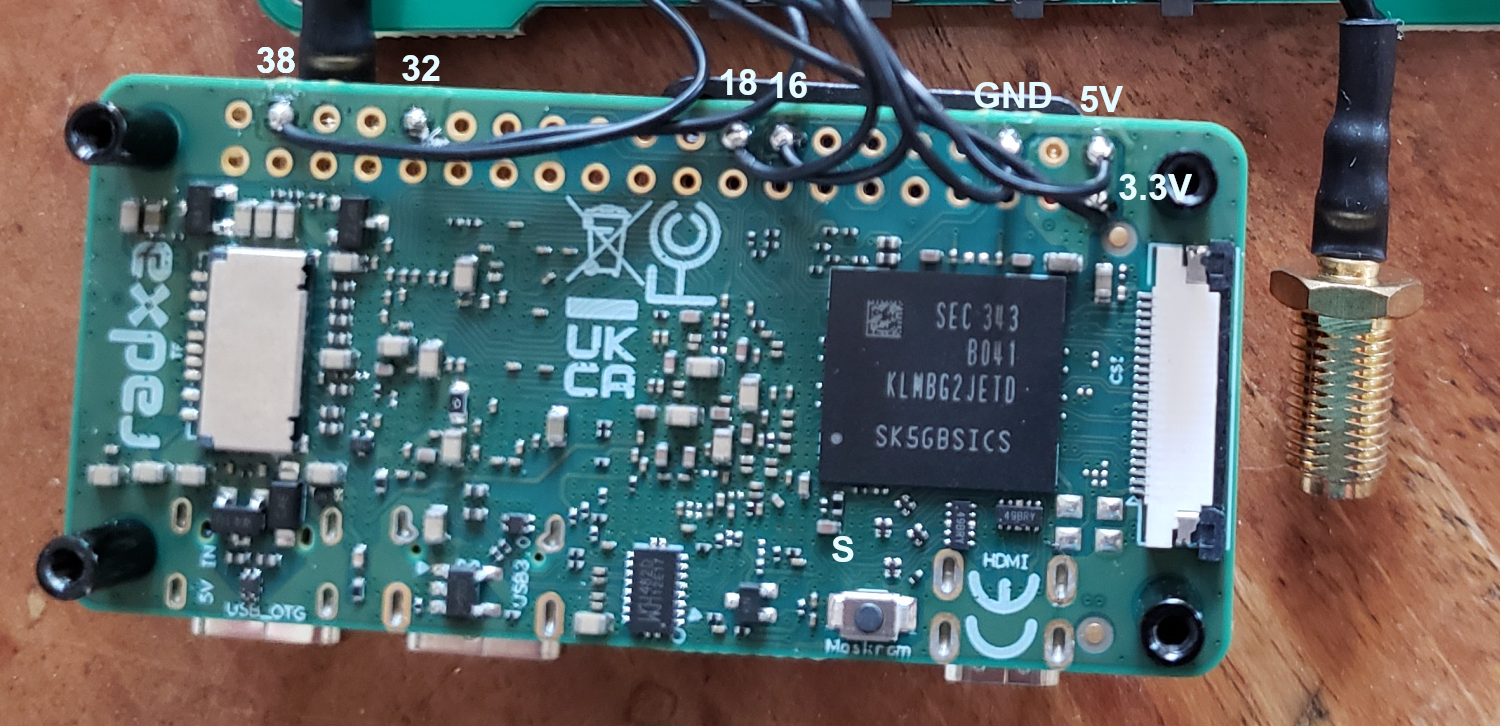
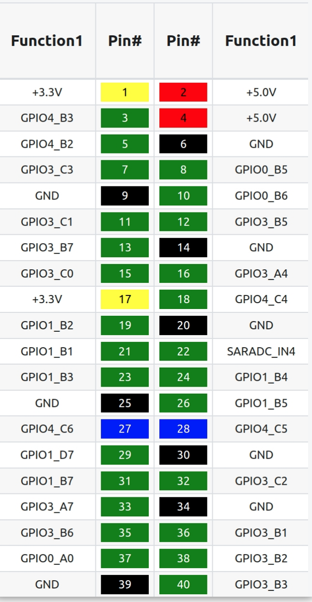
The GPIO buttons are mapped as following
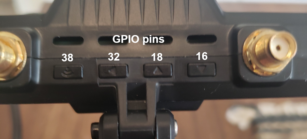
Since the Emax VRX only has 4 buttons we need to make some choices on how to map their functions for GSMenu. Here is one possible layout with the left most button as “center” and the 2nd buttons as “left” . This allows for using the GSMenu keyboard and all other GSMenu functions since right/center behaves the same for most of the menu.
gsmenu: enabled: true gpio: # Emax left: 32 center: 38 up: 18 down: 16If you prefer a more traditional mapping this might be prefered, but it lacks the center function so we can’t use the GSMenu keyboard.
gsmenu: enabled: true gpio: # Emax left: 38 right: 32 up: 18 down: 16If you prefer to think of the buttons looking at the VRX head on rather than when mounted on your goggles (from the back), you can reverse the button order
gsmenu: enabled: true gpio: # Emax left: 32 right: 38 up: 16 down: 18After editing the GPIO file, modify the setup.txt to use the matching GPIO. Here is an example setup.txt when using a new Emax.yaml file
# Set the screen_mode to your HDMI display's desired mode. Format is WxH@fps - Common values would be 1920x1080@60, 1920x1080@120. 1280x720@60, 1280x720@120[screen mode]screen_mode = 1920x1080@60
# Set the rec-fps to the fps at which your camera is shooting. e.g. 60, 90, 120[dvr recording]rec_fps = 60
# Set the gpio_layout. Accepted values are Ruby, Bonnet, Runcam, and Custom.[gpio]gpio_layout = Emax
# Setting osd to "ground" enables the vrx-side msposd_rockchip process.[msposd]osd = air