OpenIPC Bonnet
The OpenIPC Bonnet is a compact expansion board designed to extend the capabilities of small single-board computers—such as the Radxa Zero 3W—used in FPV, relay, and ground station systems. It integrates USB expansion, motion sensing, power management, and communication interfaces tailored for use with OpenIPC.
Features
- Wide Voltage Input: 2S–6S Li-ion/LiPo input via high-efficiency two-way BEC.
- Power Outputs:
- 5V and 3.3V regulated power rails.
- Integrated battery voltage monitoring.
- USB Hub: Built-in 4-port USB 2.0 hub with stable device detection.
- Wireless:
- Dual RTL8812AU Wi-Fi modules with 4x front-end modules (FEM) for extended range and bandwidth.
- Video Output:
- HDMI-to-DisplayPort bridge for connecting low-latency external screens.
- User Interface:
- 5-way joystick + tact switch for UI/OSD interaction.
- Sensors:
- 6-axis IMU (gyroscope + accelerometer).
- Expansion Ports:
- UART and I2C headers.
- Compact Design: Optimized for drone, portable, and field-based use.
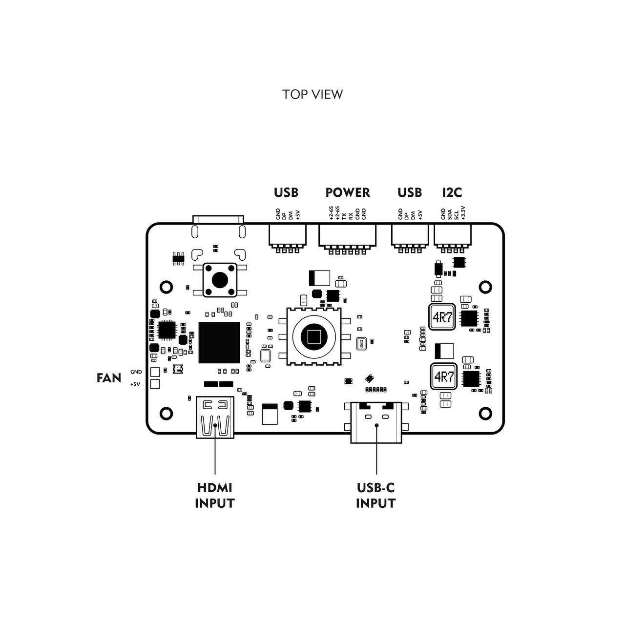
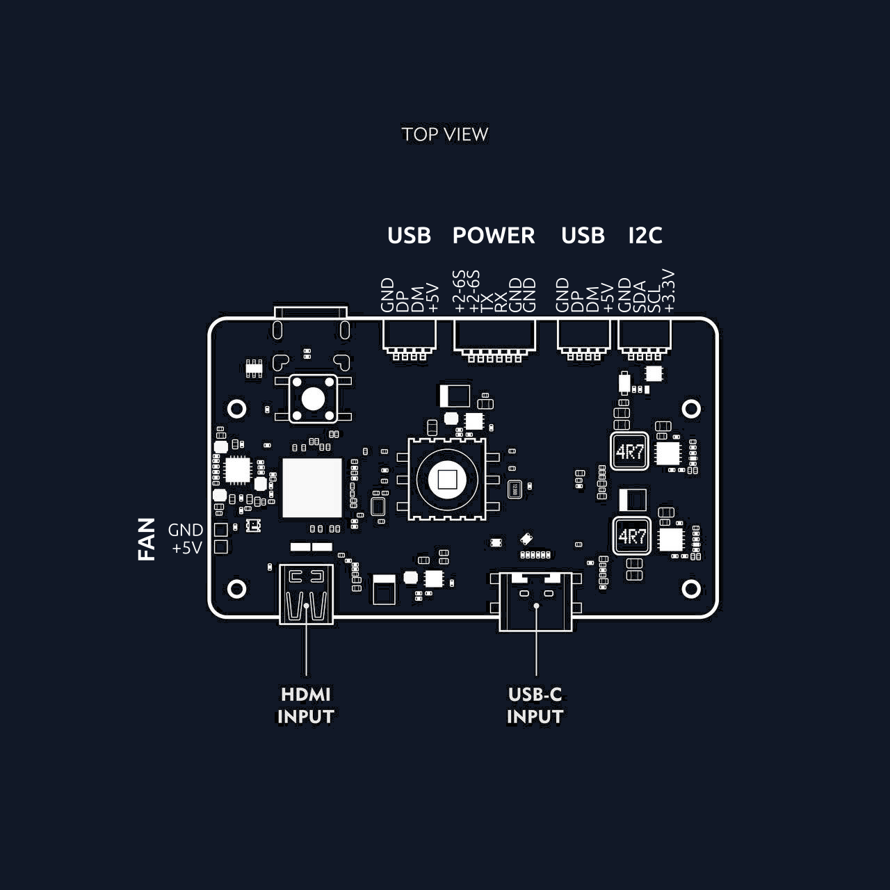
Front View Diagram
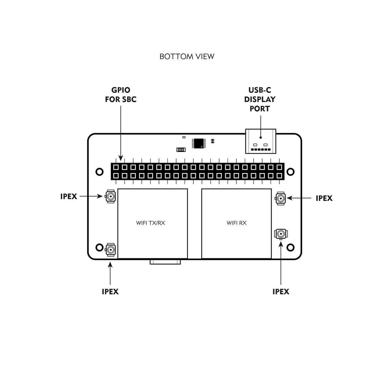
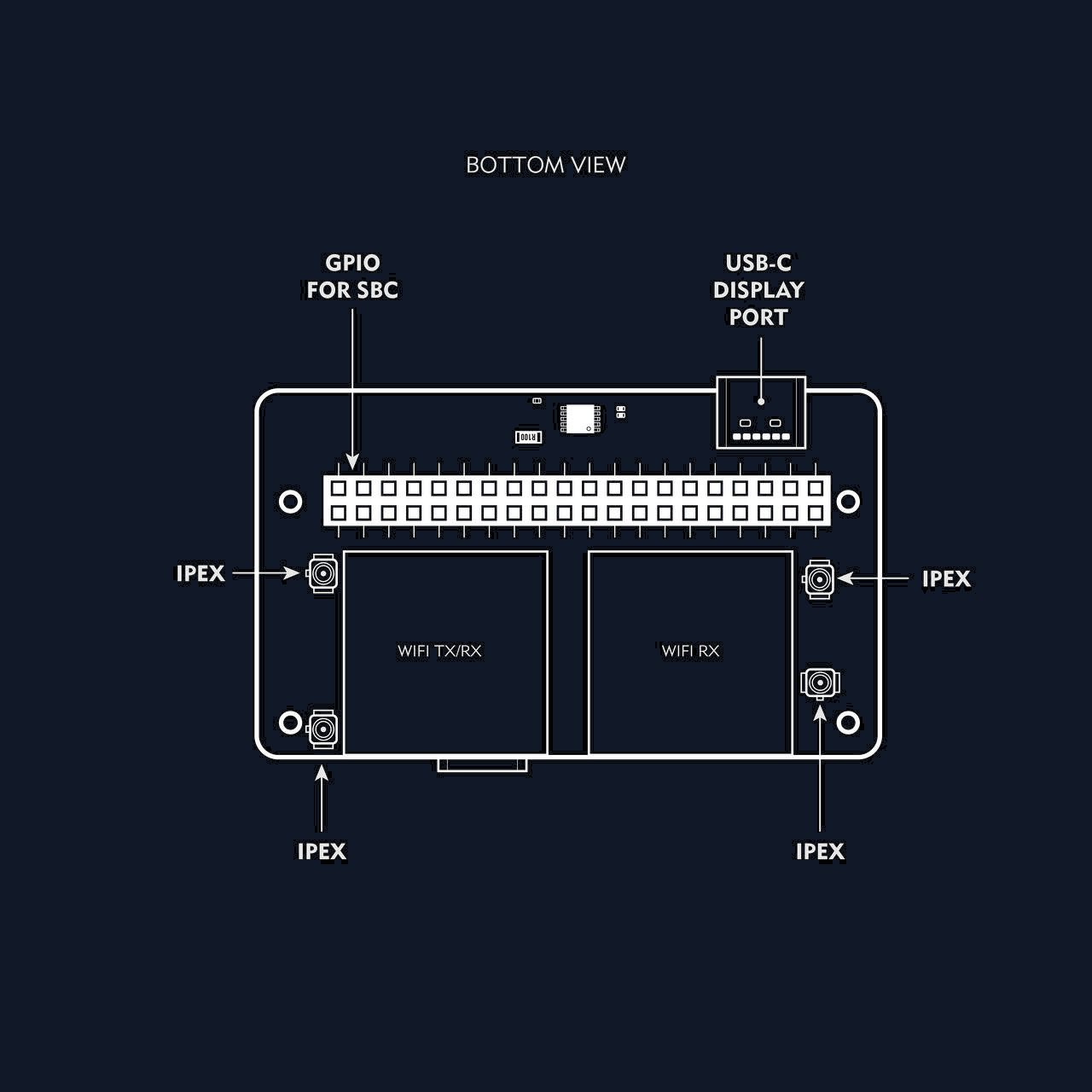
Back View Diagram
Typical Use Cases
1. Portable VRX Ground Station
Build a portable FPV ground station (VRX ), with a SBC ( Single Board Computer such as Radxa zero 3 W ) .
2. Long-Range FPV Relay Node
Deploy the Bonnet and Radxa Zero 3W in a weatherproof enclosure as a field relay station. Perfect for bridging control and video links between drones and base stations.
3. All-in-One FPV Radio Controller
Integrate into a custom RC radio build running OpenIPC, with HDMI output, ELRS, and touchscreen or physical controls. Combines control and real-time video in a single device.
4. Goggles-Mounted VRX
Pair the FPV goggles such as Meta quest 3 to create a lightweight, wearable FPV monitor with onboard decoding.
Getting Started
-
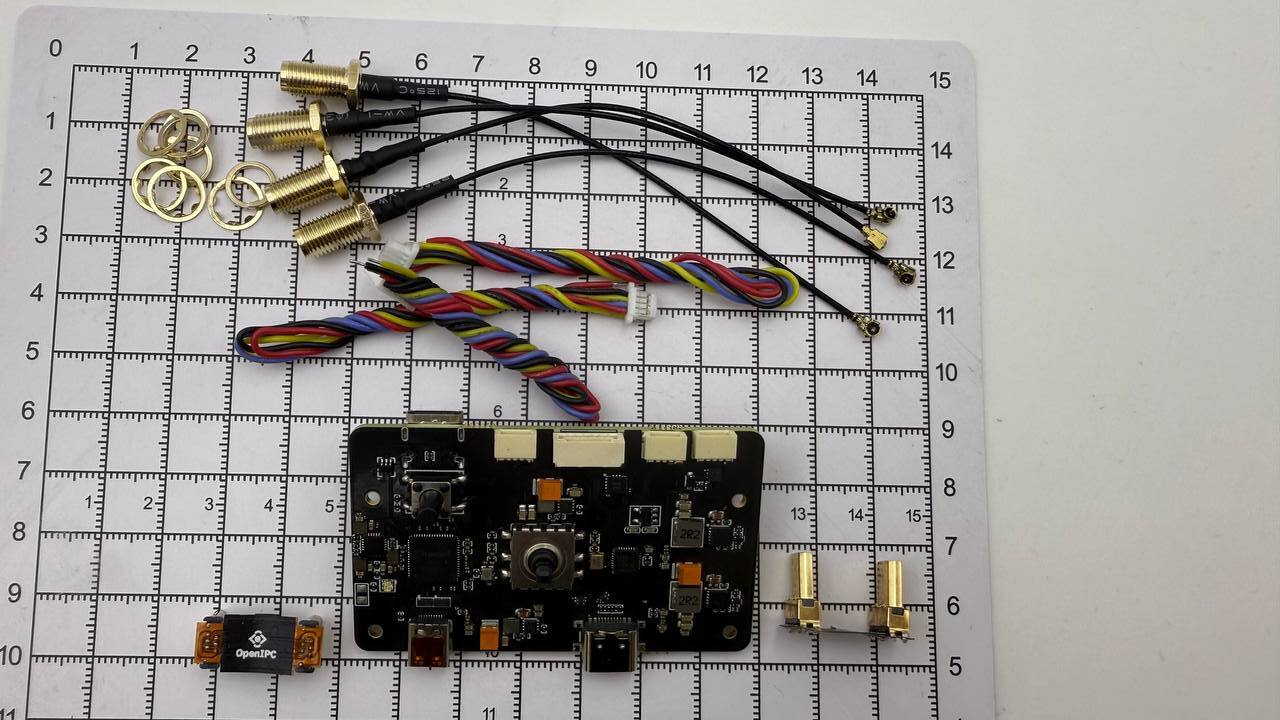
Attach Antennas
Connect antennas to the Bonnet. ALWAYS connect the antennas before powering the bonnet. There are 4 IPEX connectors. The bonnet comes with 4 ipex to SMA cables. -
Connect to SBC
Plug the Bonnet into your SBC (Single board computer such as Radxa zero 3) using the 40 pin GPIO female port and the the flexible USB dock cable.
This step is optional if you plan to use the Bonnet with Android phone or Meta Quest VR headset.
- Insert a microSD Insert a SD card with a compatible OpenIPC image flashed on it. RubyFPV is also possible.
This step is optional if you plan to use the Bonnet with Android phone or Meta Quest VR headset.
- Power Up
Connect a 2S–6S battery to the power input wires. Use the diagrams above as a reference. It’s recommended to use a jack or xt30 or xt60 connector. You will have to solder the connector yourself. The Bonnet will regulate power to the SBC and peripherals. The bonnet has polarity protection, so even if you reverse the positive and ground, you will not break the Bonnet.
Display Port Output
The OpenIPC Bonnet includes an HDMI-to-DisplayPort bridge, allowing you to connect a low-latency external monitor—ideal for FPV, debugging, or touchscreen interfaces.
To use the DisplayPort output:
- You need a micro HDMI to micro HDMI bridge connector (male-to-male or an appropriate micro HDMI cable), since the Bonnet routes video output from the SBC’s HDMI through the internal bridge.
- Ensure your monitor or display accepts DisplayPort input and supports low-latency EDID signaling.
The bridge automatically negotiates video parameters using EDID, so no special configuration is typically required. Once powered and connected properly, video should appear on the external display during boot.
Useful for attaching to a head-mounted display, small FPV monitor, or modern VR glasses.
Button Mappings
The buttons and some additional devices on the bonnet are mapped to the GPIO pins on radxa in the following manner:
- 5-way joystick:
- Up = PIN16
- Down = PIN18
- Right = PIN12
- Left (Back) = PIN13
- OK (Menu) = PIN11
- Record button: PIN22
- I2C3: Connected to IMU + INA226
- UART: PIN8 (TX) + PIN10 (RX)
Action Button
The push button is mapped to GPIO pin number 22 on Radxa zero 3. This works with SBC images for OpenIPC-FPV. It will not work with Ruby FPV. To remap the button to work with Ruby QA1 button, follow RubyFPV guidelines for custom Button mapping:
- Insert the SD card (that has Ruby flashed on it) into a PC;
- On the partition that shows up, add a new file named gpio.txt;
- Edit this new file and add 4 numbers, corresponding to the GPIO pin numbers you want to use for Menu/Back/Up/Down;
- If you want to customize the GPIO pins for the Quick Actions too, add 3 additional numbers corresponding to the new GPIO pins to be used for QA1, QA2 and QA3;
The file content should be:
11 13 18 16 22 38 40
- Save the file. Ruby will use the new GPIO mappings.
Software Notes
- Dual Wi-Fi requires the
rtl8812audriver (included in OpenIPC builds). - IMU is accessible via I2C and compatible with motion-tracking tools.
- USB hub supports common USB peripherals. You can use it to add more WiFi adapters or add a female port for copying files in Ruby.
Resources
Contributing
Want to help expand support or test new features? Check our Contribution Guidelines to get involved.